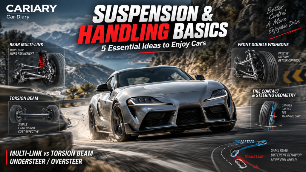
Suspension Basics can sound like a list of expensive hardware: multi-link, double wishbone, adaptive dampers. But the question that made us curious is much simpler. Why does one car feel calm and accurate on a broken road while another feels busy, even when both have plenty of power?
In Part 1, we explored how an engine produces power. In Part 2, we followed that power to the wheels. Part 3 is about what happens next: keeping those wheels useful when the road rises, the car brakes and the next corner arrives.
You do not need to calculate a suspension geometry to enjoy cars. Understanding what these parts are trying to achieve already makes a specification sheet, a driving impression and even a motorsport replay far more interesting.
Quick Summary
- Multi-link and torsion beam describe different ways of guiding rear-wheel movement, not guaranteed good and bad handling.
- Double wishbones give engineers useful control over the wheel’s angle as it moves up and down.
- An anti-roll bar resists unequal suspension movement across an axle, with trade-offs in compliance and handling balance.
- Understeer and oversteer describe the relationship between the requested turn and the car’s response, especially when grip runs short.
- Camber, toe and caster describe three different alignment angles. More aggressive is not automatically better.
The idea running through all five is this: good suspension helps the tires work, rather than merely making the body feel stiff.
Why Suspension Basics Matter Beyond Comfort
Imagine walking quickly across an uneven pavement while carrying a full cup. Locking your knees does not make you more controlled. Letting your legs move helps your feet follow the ground while your upper body remains more settled.
A car needs a related compromise. The wheels must respond to bumps, but the body cannot simply bounce, pitch and roll without control. Meanwhile, the tire contact patches, the small areas of rubber touching the road, must provide braking, cornering and acceleration forces.
There are three jobs worth separating. Springs support load and store energy as they compress. Dampers, often called shock absorbers, resist motion and dissipate energy, controlling how quickly suspension compresses and rebounds. Arms and links guide the wheel along a designed path. A damper is not just a second spring; its behavior depends on movement speed as well as its design. Ohlins’ explanation of damper flow is a useful practical example.
The structure holding everything together matters too. Mounting points that move unexpectedly can undermine carefully chosen wheel geometry. That connection is covered in our body-on-frame vs monocoque guide.
1. Multi-Link vs Torsion Beam: What Is Actually Different?
Torsion beam: simplicity with a purpose
In a typical torsion-beam rear suspension, each rear wheel is carried by a trailing arm. A crossmember connects the two arms and is designed to twist when their movements differ. This makes the system semi-independent: one wheel can move differently from the other, but the two sides are mechanically coupled.
That twisting crossmember is not a differential or a drive axle. The familiar layout on many front-wheel-drive cars is a non-driven rear assembly.
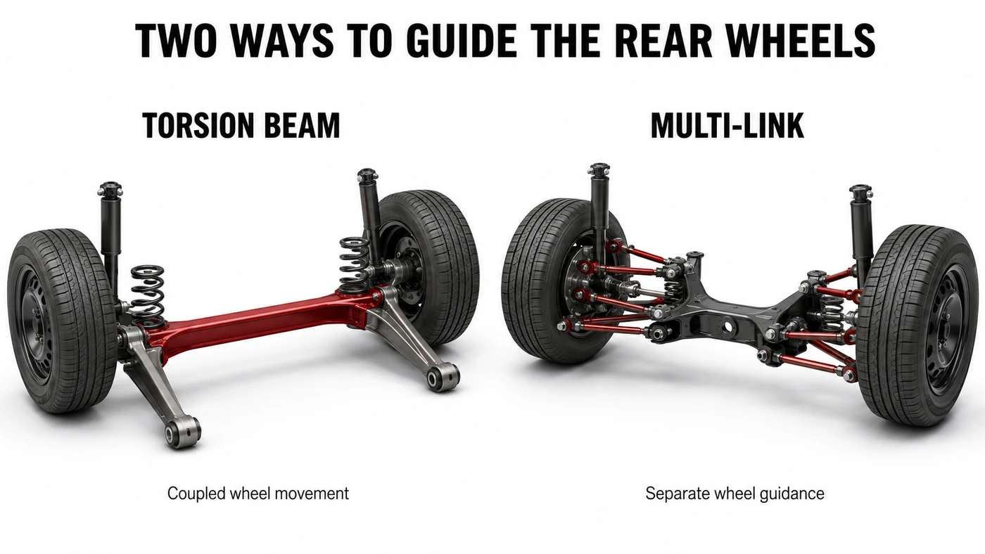
Fewer separate arms and joints can make the assembly economical to produce and compact to package beneath rear seats and luggage space. There may also be fewer wear points to service. Those are useful engineering advantages, not merely excuses for spending less.
The limitation is freedom. Because the two trailing arms are connected, engineers cannot choose every aspect of each wheel’s movement independently. A bump affecting one wheel can influence the other side, and tuning wheel-angle changes involves the beam’s shape, stiffness and bushings together. Bushings are compliant joints, often rubber-based, that allow controlled movement while isolating vibration.
Multi-link: more ways to shape the wheel’s behavior
A multi-link suspension uses several links to locate each wheel carrier. Together, they control its position and orientation as it moves. Some mainly resist fore-and-aft forces; others help control lateral movement or alignment. Their actual jobs depend on the geometry rather than a universal one-link, one-function rule.
That gives engineers more freedom to balance ride comfort, cornering behavior and changes in camber and toe. It also means more components and joints, with potential cost, service and packaging penalties. Clever designs can be compact, so even the packaging comparison is not absolute.
Honda’s five-link rear suspension development notes are a helpful example: the company used link placement to pursue both wheel control and passenger-space efficiency.
So is multi-link always better?
No. It offers more tuning possibilities, not a certificate of superior execution. Tire choice, damper calibration, spring rates, bushing compliance and the vehicle’s mass all help determine the result. Spring rate describes how much extra force is needed for a given additional compression; compliance means how readily a part or joint deflects under load.
Mazda introduced a torsion-beam rear layout on the all-new Mazda3 presented in 2019, alongside a broader effort to coordinate the tires, body and seating. That is a useful reminder to assess the complete system rather than one line in a brochure. Mazda’s vehicle-architecture explanation describes that approach.
| Layout | Useful strengths | Main trade-offs |
|---|---|---|
| Torsion beam | Compact assembly, fewer separate joints, production simplicity | Coupled wheel movement and fewer independent geometry choices |
| Multi-link | More freedom to shape wheel movement and compliance | More parts, development complexity and potential service cost |
2. Double Wishbone: Why Two Arms Can Make a Difference
A double-wishbone suspension locates the wheel upright with an upper and a lower arm. The upright is the part that carries the wheel hub and connects it to the suspension. Seen from above, a wishbone commonly resembles an A, with two inner mounting points and an outer joint.
The important feature is not the attractive shape of the metal. It is the relationship between the two arms.
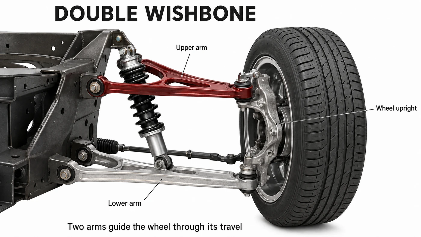
As the wheel moves upward relative to the body, the arms swing through arcs. Their lengths and mounting positions determine how the wheel tilts and shifts. A shorter upper arm is commonly used to make the top of the wheel move inward during compression, creating negative camber gain relative to the body.
Why bother? In a corner, the body can roll outward. Geometry that changes wheel angle appropriately can help the loaded outside tire maintain a useful orientation to the road. It does not guarantee that the tire stays perfectly flat or that pressure is identical across its tread.
There are costs: two arms and their mounting space must fit around the wheel, steering, brakes and body. The design also needs careful tuning through its full travel, not just at the parked ride height. MathWorks’ double-wishbone model documentation illustrates how geometry, spring and damper behavior belong in the same system.
A sports-car example, not a universal ranking
The 992.1-generation Porsche 911 GT3 introduced in 2021 used a double-wishbone front axle derived from Porsche’s racing experience. It is a clear example of choosing this layout for demanding wheel control. Porsche’s GT3 chassis explanation also describes the multi-link rear suspension.
But double wishbone does not automatically defeat multi-link, and those names are not always separate boxes. Honda even described the five-link design above as a double-wishbone system. Manufacturers may split a traditional arm into separate links or use different naming conventions.
The useful question is: what wheel movement does this particular design allow?
3. Anti-Roll Bars: Less Lean, but Not Free Grip
An anti-roll bar, stabilizer bar and sway bar are usually three names for the same device. In a conventional arrangement, a torsion bar connects the left and right suspension through lever arms and end links. Bushings attach its central section to the chassis or subframe.
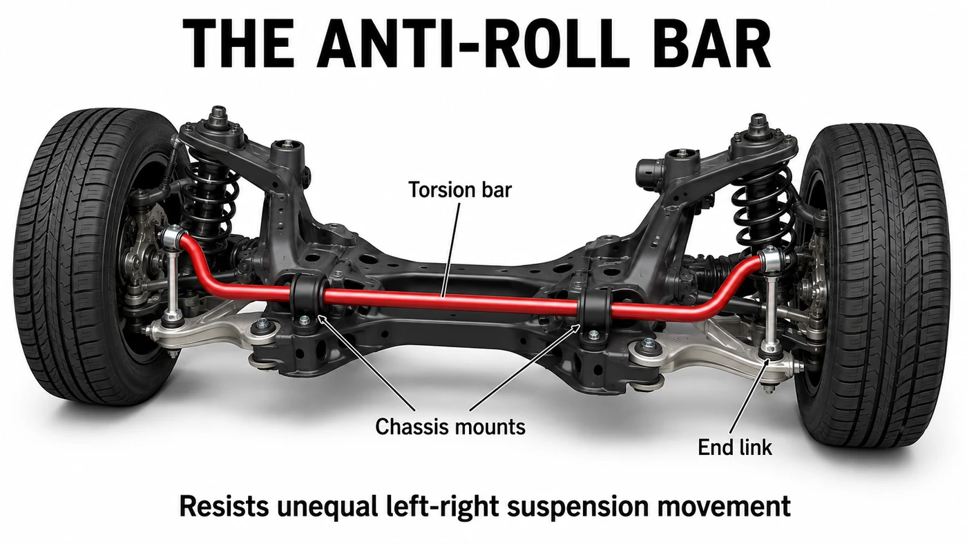
If both wheels rise together by the same amount in an ideal symmetric system, the bar can rotate in its mounts with little torsional deflection. If one side compresses more than the other, the ends try to move differently. The bar twists and resists that difference. ZF’s stabilizer-link overview explains the links that connect it to the suspension.
Picture a left-hand corner. The right side is outside the turn. The body tends to lean right, compressing the outside suspension and extending the inside suspension relative to the body. The anti-roll bar helps resist that difference in travel.
Why a thicker bar is not an automatic upgrade
Increasing roll stiffness can limit body motion and help control geometry. But an anti-roll bar also couples the two sides when a single wheel encounters a bump. Too much stiffness for the application can compromise rough-road compliance or unload an inside tire more strongly.
It can change handling balance as well. All else equal, increasing the front axle’s share of roll stiffness often promotes understeer; increasing the rear share often promotes oversteer. These are tendencies, not setup instructions. Camber changes, tires, bump stops and whether the car is entering or settled in a corner can alter the outcome.
The reason involves tire load sensitivity: adding vertical load to a tire usually does not increase its cornering capacity in direct proportion. The more heavily loaded tire may gain less capability than its unloaded partner loses. A bar therefore changes how the tire pair works, not just how level the roof looks. OptimumG’s discussion of load transfer explains this distinction.
Body roll and load transfer are not the same thing
Body roll is visible leaning. Load transfer is the change in how much vertical load different tires carry. A very stiff car can transfer substantial load with almost no visible lean.
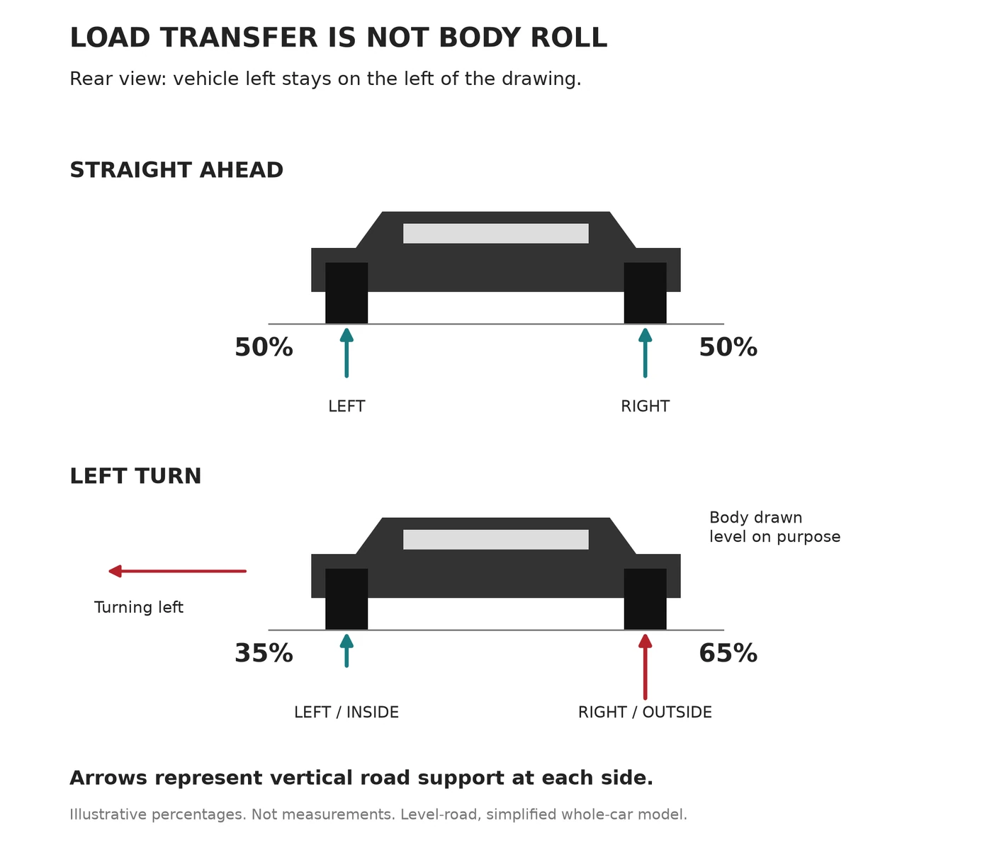
In our deliberately simplified example, both sides carry 50% while traveling straight. During a left turn, the right side carries 65% and the left carries 35%, despite the level body in the drawing. These are teaching values, not measurements or a target distribution.
On a level road, braking generally increases front tire loading, acceleration increases rear loading, and cornering increases outside loading. Detailed suspension geometry and body movement influence how this develops. But making the body look flat does not remove the forces that cause it. OptimumG’s explanation of geometric and elastic load transfer explores those different routes through the suspension.
4. Understeer vs Oversteer: Which End Runs Short of Grip?
These words become much easier when we separate where the wheels point, where the car is moving and where the body is pointing. They are related, but they are not always identical.
Understeer: the car turns less than requested
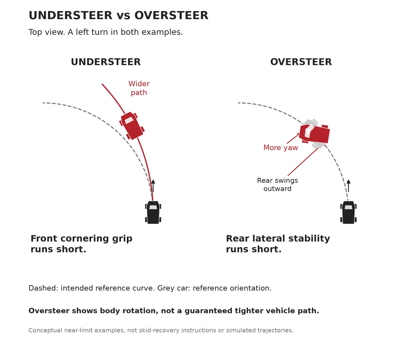
Near the grip limit, the front tires can run out of the lateral force needed for the requested turn. The car then runs wider than the driver intends. More steering angle does not necessarily provide more cornering force once the tires are beyond their useful range.
You may hear a commentator describe this as the car pushing wide. It is not exclusively a front-wheel-drive behavior. Any layout can understeer, depending on speed, loading, tire condition, road surface and setup.
Oversteer: the rear loses lateral stability
When the rear loses lateral grip relative to the front, the car can rotate more than intended and its rear can swing outward. That rotation is called yaw. If it develops too far, a spin can follow.
Oversteer is not simply a better way to take a tighter corner. A car can rotate sharply while its center of mass continues sliding toward the outside. Dramatic body angle is not proof of a controlled or faster trajectory.
Engine torque can trigger rear-tire slip, but it is not the only cause. Braking, an abrupt change in throttle, uneven grip or the car’s setup can also disturb rear stability. Front-wheel-drive cars are not immune.
These terms also exist before a slide
Engineers use understeer and oversteer to describe steering response as cornering demand increases, not only spectacular loss-of-grip moments. A car can have a mild understeer tendency while all four tires are still operating normally. The limit examples above are simply the easiest ones to visualize.
Many road cars are tuned for a progressive, manageable response rather than maximum willingness to rotate. A circuit driver may prefer a different balance, but neither neutral handling nor oversteer is automatically safest or fastest in every situation.
Electronic stability control compares intended and actual vehicle motion and can intervene with individual-wheel braking and power reduction. It helps manage instability; it cannot create unlimited tire grip. Bosch’s ESP explanation describes the principle. Exploring the limits belongs in a controlled training environment, not on public roads.
5. Camber, Toe and Caster: Look from Three Different Directions
Wheel alignment is not simply making every wheel perfectly vertical and parallel. Engineers choose angles for a particular vehicle, its tires and the way its suspension changes shape under load.
The quickest way to stop mixing them up is to change your viewpoint: camber from the front, toe from above, caster from the side. Michelin’s alignment guide provides an accessible introduction to those three views.
Camber: the wheel’s inward or outward tilt
Viewed from the front or rear, negative camber means the top of the wheel tilts toward the vehicle’s center. Positive camber means it tilts outward.
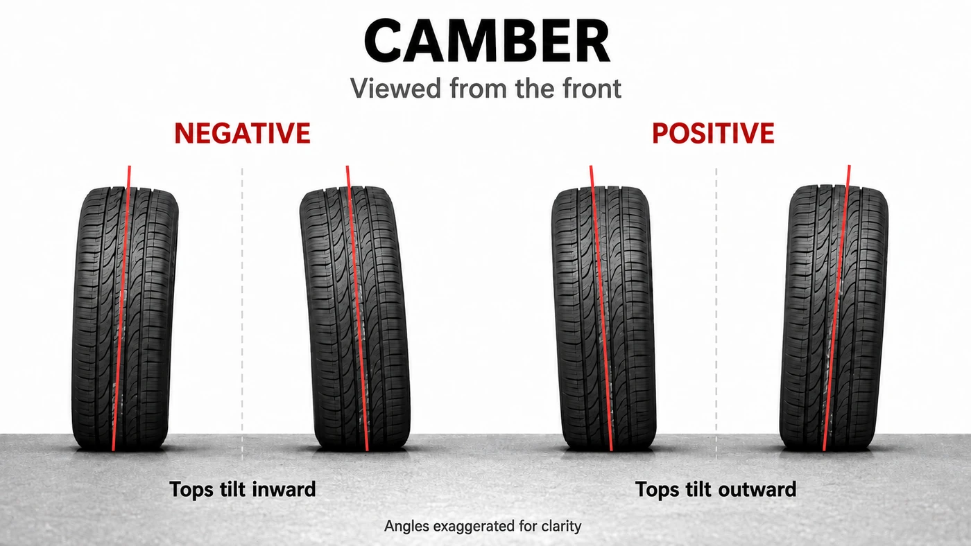
Negative camber can help a loaded tire work during cornering, when body roll, suspension movement and tire deformation would otherwise change its orientation. That does not mean adding more always creates more grip.
Excessive negative camber for the application can bias straight-line loading toward the inner tread and compromise wear or braking performance. The goal is suitable pressure distribution under the relevant conditions, not a dramatic parked stance. A tire’s construction and operating load matter as much as the number printed on an alignment sheet.
Toe: where the leading edges point
Now look down from above with the steering centered. If the leading edges of the two wheels are closer together than their trailing edges, that is toe-in. If the leading edges are farther apart, that is toe-out.
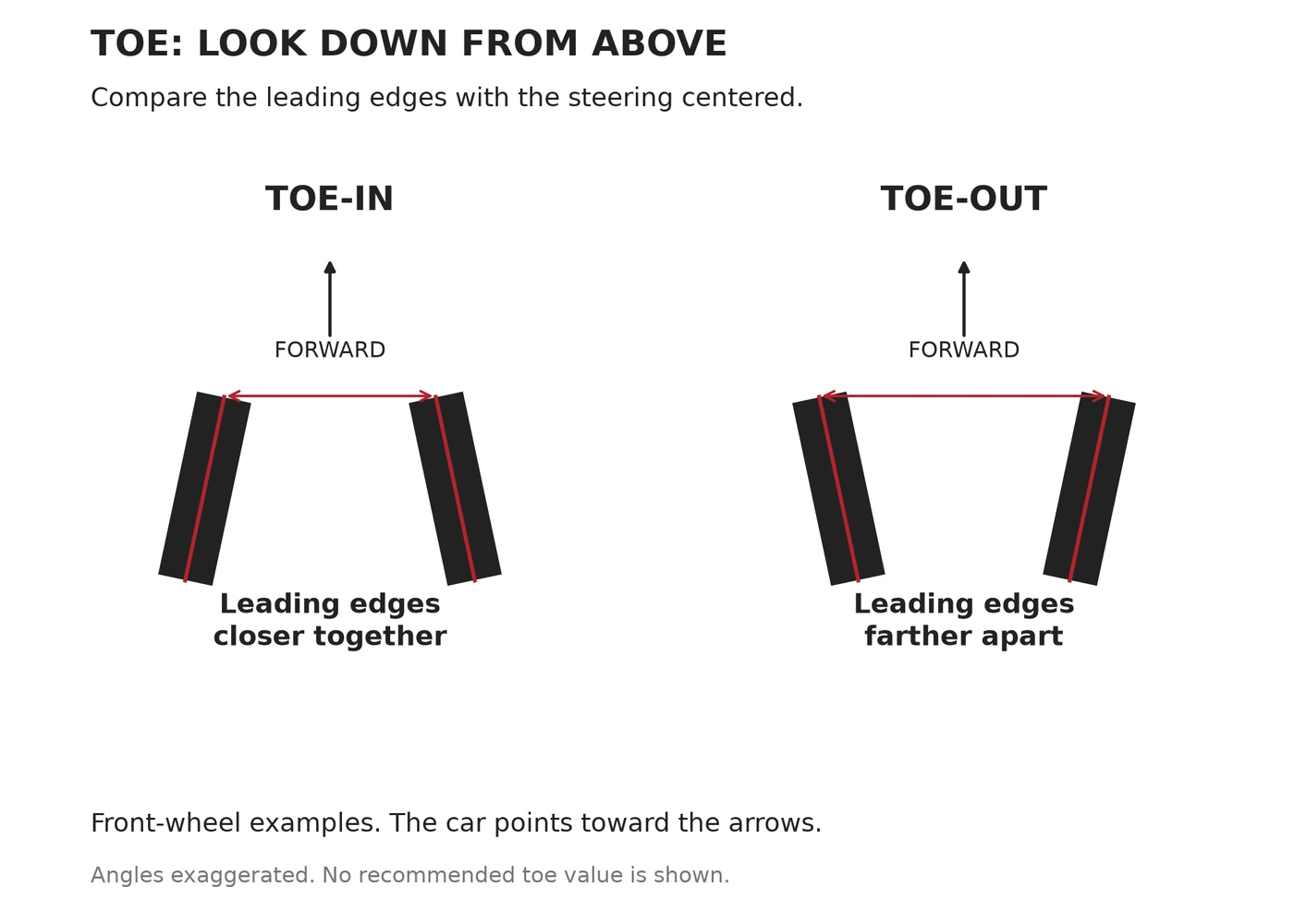
Small toe changes can have a noticeable effect on steering response and stability. Rear toe-in is commonly used to encourage stability; some performance applications use front toe-out to influence initial response. Neither is a universal recommendation, and rear toe-out should not be treated as a casual road-car upgrade.
Toe also changes as suspension moves and its rubber joints deflect. What an alignment rack measures while stationary is not necessarily the angle under braking or cornering. Excessive toe can produce tire scrub, heat and wear even when the car appears to drive straight. OptimumG’s analysis of toe gain and compliance shows why loaded behavior matters.
Caster: the steering axis, not the wheel face
Look at a front wheel from the side. Caster is the fore-and-aft tilt of the axis around which the wheel steers. With positive caster, the top of that axis leans rearward.
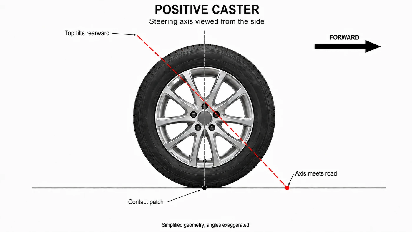
In the simplified geometry shown, the steering axis reaches the road ahead of the tire contact patch. The contact patch trails that point, creating a lever arm called mechanical trail. Tire forces acting through this geometry can contribute to the steering’s tendency to return toward straight ahead.
Caster angle and trail are related, but not identical: wheel-center offset and the rest of the geometry also matter. Tire deformation creates its own aligning effects, while steering assistance, friction and geometric lifting effects influence what reaches the driver’s hands. Caster is not the sole source of self-centering.
Caster can also change camber as the wheels steer. This is why it belongs in the discussion of cornering behavior, rather than only straight-line stability. More is not automatically better; a car’s steering and suspension are designed as a package.
| Angle | Viewing direction | What it describes | What to remember |
|---|---|---|---|
| Camber | Front or rear | Wheel top leaning inward or outward | Cornering orientation and tread loading |
| Toe | Above | Leading edges closer together or farther apart | Response, stability and tire scrub |
| Caster | Side | Steering axis leaning forward or rearward | Steering geometry, trail and return tendency |
Do not use the exaggerated image angles as settings. Correct specifications depend on the exact model, ride height, load condition and approved procedure. Some angles are not adjustable with the original hardware. Uneven wear or a steering concern deserves inspection by a qualified technician, not an internet-wide alignment number.
Reading a Suspension Specification Without Ranking the Labels
Suppose a brochure says double wishbone front, multi-link rear and adaptive dampers. We can infer that the designers have particular tools for guiding the wheels and controlling motion. We cannot infer the ride quality or handling balance without understanding how those tools were used.
An adaptive damper changes damping behavior; it does not inherently change the spring rate. Air suspension replaces or supplements conventional springing with compressed gas, allowing features such as load leveling and height adjustment depending on the design. Active roll control adds actuators to counter body roll rather than relying only on a passive twisting bar. These are different jobs, even when a manufacturer combines them under one chassis-system name. ZF’s active-chassis overview distinguishes damping and roll-control functions.
The distinction helps explain why an expensive car can offer several modes without turning into an entirely different mechanical design. Electronic control broadens the available behavior, but tire capabilities, suspension travel and packaging still set boundaries.
Three real-world lessons
The Mazda3 example shows why a torsion beam should not end the discussion. The 911 GT3 shows why precise wheel guidance can justify a double-wishbone design. And the 2021 BMW M3/M4 chassis provides an important counterpoint: BMW explained that its multi-link strut front construction met its requirements with fewer parts and lower weight than the alternative under discussion.
BMW also described matching tires, camber and toe through extensive testing. That is more revealing than assuming a suspension name alone determines capability. BMW M’s chassis-development Q&A makes the complete-system approach clear.
Common Misconceptions: Stiff Does Not Automatically Mean Fast
A comfortable car must handle badly. Comfort and control are not opposites. A wheel that can follow a rough surface may use its grip more consistently than one being jolted across it. Too little control is a problem too: excess travel, poor damping or repeated bump-stop contact can upset the car.
A flat body means no load transfer. The tires still have to generate the forces that turn and slow the car. Less visible roll does not mean equal loading.
Every multi-link car is better than every torsion-beam car. Architecture creates possibilities. Tires, geometry, calibration and condition decide how much of that potential becomes useful.
Negative camber is a free cornering upgrade. An angle that suits a specific track tire and load condition may be unsuitable for ordinary road use. Excess camber and toe can produce expensive consequences without delivering the intended benefit.
Oversteer proves a car handles well. Rotation can be useful in trained hands on a circuit, but an unexpected loss of rear stability is not a quality badge. Predictability matters more than spectacle.
Cariary Thoughts
What changes our view most is realizing how little the suspension name tells us by itself. It is tempting to build a simple ladder: torsion beam at the bottom, multi-link above it, racing hardware at the top. The engineering refuses to stay that tidy.
A supposedly simple design can be carefully developed. An elaborate one can still be let down by poor calibration or unsuitable tires. Even the satisfying sight of a car cornering flat is only one clue, not the whole result.
For us, the better question is becoming: what are the tires being asked to do, and is the rest of the car helping them? That connects the engine and drivetrain lessons to something we can actually notice on an ordinary journey: whether the car settles after a bump, responds progressively and makes the road easier to understand.
Learning suspension basics does not require us to become setup engineers. It gives us a better way to ask why a car feels the way it does.
One-Line Summary
Good suspension is not about making a car as stiff as possible; it is about guiding the wheels and managing movement so the tires can work predictably.
FAQ
Is multi-link suspension always more comfortable than a torsion beam?
No. Multi-link offers more independent tuning opportunities, but comfort also depends on tires, springs, dampers, bushings and the road. The layout alone does not determine the result.
Why do performance cars use double-wishbone suspension?
It gives engineers useful control over wheel orientation through suspension travel. That can help manage the loaded tire’s position during cornering, at the cost of space and complexity. Other layouts can also produce excellent handling.
Does a stronger anti-roll bar give a car more grip?
Not automatically. It changes roll behavior, left-right coupling and handling balance. A setting that helps on one surface or at one axle may compromise compliance or the tire pair’s combined capability elsewhere.
What is the simplest difference between understeer and oversteer?
Near the limit, understeer commonly means the front runs short of cornering grip and the car pushes wide. Oversteer means the rear loses lateral stability and the car rotates more than intended. Both can occur with any drivetrain layout.
Are camber and caster the same angle?
No. Camber is the wheel’s sideways tilt seen from the front or rear. Caster is the steering axis’s fore-and-aft tilt seen from the side. Toe requires a third viewpoint, from above.
Should road cars use racing alignment settings?
Not by default. Racing settings target particular tires, loads and operating conditions. Road specifications balance predictable behavior, braking, wear and everyday use. Follow the vehicle’s specifications and obtain qualified advice for a specific application.
Is the stiffest suspension mode always the best one?
No. A very firm setting can be unsuitable for a bumpy surface. The right behavior depends on damping, travel, tires and road conditions, not simply the most aggressive mode name.
Related Thoughts
- Part 1: Engine Power Basics explores displacement, turbocharging, torque and power before that energy reaches the wheels.
- Part 2: Drivetrain Basics follows power through differentials, gearing and drive layouts.
- Body-on-Frame vs Monocoque explains the structures that support the suspension and the rest of the car.
References
Data Reference Date: September 7, 2026. Model examples identify the relevant generation or announcement; layouts can differ between versions.
- Mazda: cohesive vehicle architecture and the 2019 Mazda3
- Honda: five-link double-wishbone rear suspension development
- Porsche: the 992.1 911 GT3’s suspension
- BMW M: M3 and M4 chassis-development questions
- Ohlins: damper flow and wheel control
- MathWorks: double-wishbone suspension modeling
- ZF: stabilizer links
- OptimumG: load transfer and tire behavior
- OptimumG: geometric and elastic load transfer
- OptimumG: toe gain and compliance
- Michelin: wheel alignment and balancing
- Bosch: electronic stability control
- ZF: active damping and electromechanical roll control
Illustrations show generic teaching principles, not manufacturer drawings, measured handling data or recommended adjustment values. The image captions identify generated illustrations and original Cariary graphics.