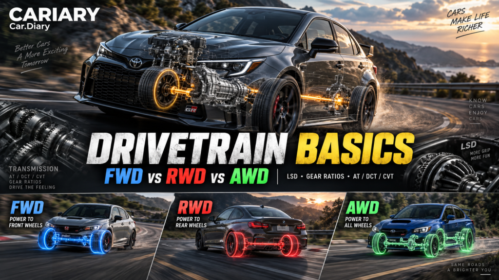
Two cars can make the same horsepower and still feel completely different. One pulls neatly out of a corner, another spins an inside wheel, and a third seems to pause before accelerating. Drivetrain Basics starts with that curiosity: what happens between the engine making power and the tires using it?
This is Part 2 of Car Basics for Enthusiasts. In Part 1: Engine Power Basics, we explored how an engine produces torque and power. Now we follow that output through the transmission, differentials and driven wheels. These are not five unrelated acronyms to memorize. They are five parts of the same story.
Quick Summary: Drivetrain Basics in Five Questions
| Question | Component or idea | What it changes |
|---|---|---|
| Which wheels receive drive? | FWD, RWD and AWD | Where the car applies its driving force |
| How can the wheels turn at different speeds? | Differential | Smooth cornering without forcing both driven wheels to match |
| What happens when one driven tire loses grip? | LSD and e-LSD | How much useful torque can reach the other wheel |
| Why does first gear feel stronger than top gear? | Gear ratio and final drive | The trade between rotational speed and torque |
| How does the car select and connect those ratios? | AT, DCT and CVT | Launch behavior, shifting and engine-speed behavior |
The important distinction is simple: the engine produces power; the drivetrain changes how that power reaches the road. Neither can tell us the whole story without the tires, chassis and control software.
Why This Matters: Read Beyond the Horsepower Number
Imagine reading two fictional specifications: 3.0-liter turbo, RWD, eight-speed AT, e-LSD, and 2.0-liter turbo, FWD, DCT, LSD. It is tempting to compare the engines and skip everything after them.
But those remaining terms describe what happens when the driver asks the car to move. They help explain a smooth parking maneuver, a crisp upshift, an eager corner exit or an engine that holds a steady note while road speed rises.
For a conventional front-engine, rear-wheel-drive car, the basic route is engine, clutch or torque converter, gearbox, propshaft, final drive and differential, halfshafts, then wheels. A propshaft carries rotation along the car; halfshafts carry it from a differential to the individual wheels. In other layouts, several of these components share one housing, or the propshaft is absent.
An electric motor changes the starting point, not the underlying questions. It still needs a way to deliver torque to the wheels, usually through reduction gearing. This installment focuses on familiar combustion-engine layouts so we can build that understanding one step at a time.
1. FWD, RWD and AWD: Which Wheels Do the Driving?
FWD: Compact Packaging, Shared Front-Tire Work
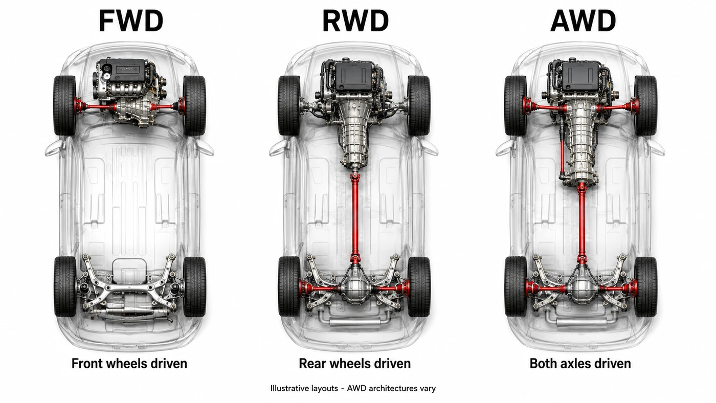
Front-wheel drive sends driving torque to the front wheels. In a common transverse layout, the engine sits across the car, with the transmission and front differential packaged beside it. A combined transmission-and-axle-drive assembly is called a transaxle.
Putting the major components together creates a compact package that can be installed efficiently during production. A conventional FWD car does not need a long rear propshaft and a separate rear-drive differential. That often reduces cost, mass and mechanical losses while freeing useful cabin space. It helps explain why the layout suits so many hatchbacks, family cars and crossovers.
The front tires steer and also provide the driving force. That does not mean the rear tires do nothing: all four tires contribute to braking and cornering. The specific challenge is asking the front pair to combine substantial acceleration with steering, within a limited amount of tire grip.
Understeer means the car turns less than the driver requests and runs wider than intended. FWD can encourage it when the front tires are heavily loaded with combined tasks, but any drivetrain can understeer. Torque steer is a pull through the steering under acceleration; driveshaft geometry, suspension compliance and steering design all influence it. Neither behavior is an unavoidable verdict on every FWD car.
RWD: Separate the Driving and Steering Axles
Rear-wheel drive applies driving torque at the rear. The front wheels can steer without also transmitting engine torque, although they still carry cornering and braking loads.
Under acceleration, load transfers toward the rear axle. That can help the driven rear tires transmit more force. The driver can also feel how throttle input changes the rear tires’ workload through a corner, which is part of RWD’s appeal in performance cars.
This is not a promise of perfect balance or superior stability. Engine location, tires, suspension and electronic controls remain decisive. A front-engine RWD car can also be less willing to pull away on snow than a comparable FWD car with more static weight over its driven wheels. Layout is a useful clue, not a complete prediction.
AWD: More Places to Apply Driving Force
All-wheel drive can deliver driving torque to both axles. When two driven tires cannot use all the available engine torque, involving the other pair can improve acceleration traction. That is valuable for powerful launches and for moving on slippery surfaces.
The hardware varies. Some systems use a center differential; others control an axle connection with a clutch. Some can disconnect driveline components to reduce drag when extra traction is unnecessary. Magna’s Flex4 description is one example of this disconnect approach. Electrified AWD may instead use a separate rear motor, without a front-to-rear propshaft.
Additional hardware usually brings weight, cost and losses, even when clever disconnection reduces them. More importantly, AWD is not a guarantee of better cornering or shorter emergency stops. All four wheels already have brakes, and AWD cannot create tire grip that the surface does not provide. Ford’s owner guidance explicitly separates improved low-traction acceleration from stopping performance.
Is AWD the Same as 4WD?
Often, AWD describes a system that manages road-going traction automatically, while four-wheel drive, or 4WD, suggests off-road provisions such as a selectable low range or locking modes. Low range adds reduction gearing for controlled low-speed work.
However, manufacturers do not use the names consistently. Some 4WD systems have automatic modes, and some operate full-time. Read the actual hardware and owner’s manual rather than relying on the badge. A locked part-time system can bind on high-grip pavement; it is not simply an AWD setting to leave engaged everywhere.
For the wider comparison, our FWD vs RWD vs AWD guide connects these layouts to everyday driving environments.
2. The Differential: Why Two Driven Wheels Need Different Speeds
Picture two people walking around a bend side by side. The person on the outside must cover more distance. A car’s wheels face the same problem.
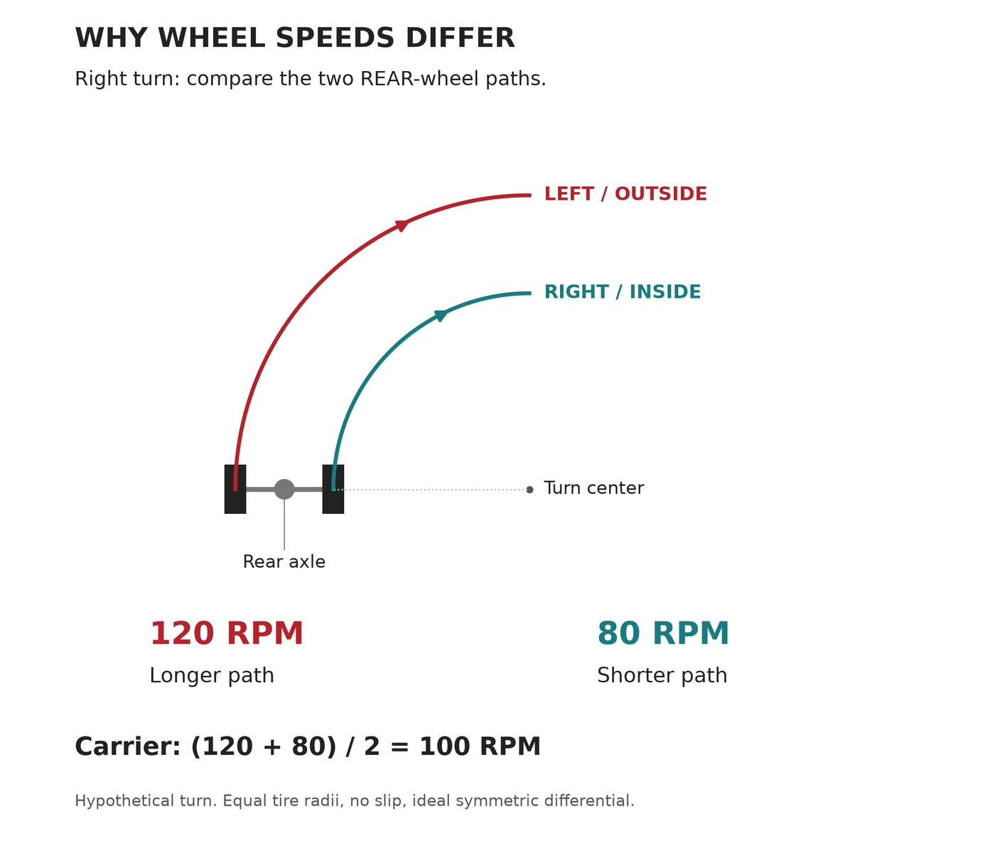
In a right turn, the left rear wheel is outside the turn and travels farther than the right rear wheel. With equal effective tire sizes and no tire slip, it must rotate faster. Rigidly forcing those wheels to match would require a tire to scrub against the road.
A differential is the geared mechanism that lets the two outputs rotate at different speeds while still receiving drive. It is usually integrated into a transaxle on a conventional FWD car and into the rear final-drive assembly on a conventional RWD car.
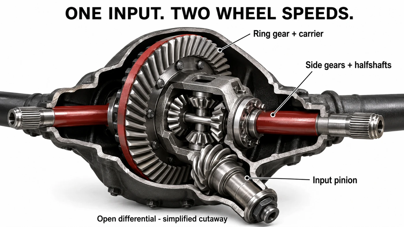
In the illustrated rear-drive arrangement, the input pinion turns the large ring gear and its attached carrier. Inside that carrier, small bevel gears connect the two side gears leading to the halfshafts. Their relative movement permits the wheel-speed difference. The ring-and-pinion reduction and the differential action are two different jobs housed together.
A Simple Cornering Example
For an ideal symmetric differential, carrier speed is the average of the two wheel-output speeds. If both outputs turn at 100 RPM in a straight line, the carrier also turns at 100 RPM. During a hypothetical turn, 120 RPM outside and 80 RPM inside give the same average.
Those are teaching numbers, not a prescribed cornering speed or a measurement from a real car. Their purpose is to show why different wheel speeds are normal, not evidence that a tire has lost traction.
Why an Open Differential Can Struggle on Ice
Now put one driven tire on a slippery patch and the other on a grippier surface. An ideal, symmetric open differential delivers approximately equal torque to its two outputs. If one side can support only a small amount before spinning, that limits useful torque at the other side too.
Suppose the slippery side can sustain 100 Nm at its wheel. In a simplified steady example, the other side also receives about 100 Nm, even if its tire could use much more. There may not be enough combined driving force to move the car.
This is different from saying that all the torque goes to the spinning wheel. Torque and power are not interchangeable. Power depends on torque and rotational speed, so the faster-spinning side can absorb much more power while the output torques remain similar. That distinction makes the next component much easier to understand.
3. LSD and e-LSD: Make More of the Available Grip
An LSD, or limited-slip differential, adds resistance to differential action. It can allow unequal output torques, helping the tire with more available traction contribute more useful driving force. It does not manufacture additional tire grip.
There are different ways to create that resistance. A clutch-type unit presses friction plates together. A helical-gear unit uses forces and friction within its gearing. Eaton’s limited-slip overview describes both approaches; they share a purpose without being mechanically identical.
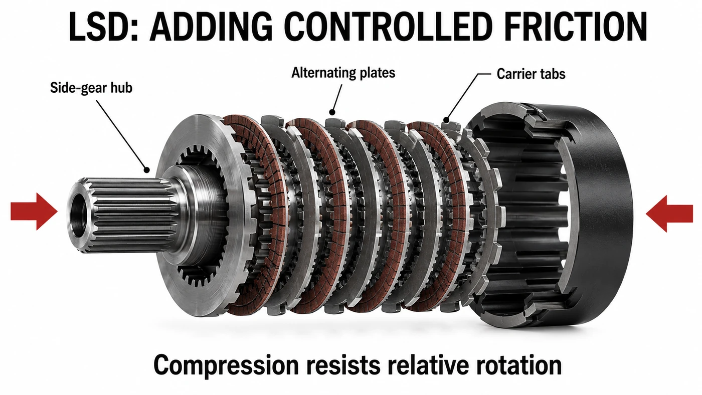
The plate illustration shows the principle of coupling a side-gear hub to the carrier through alternating plates. As clamping force increases, friction opposes relative movement. It is a component explanation, not a complete differential or an assembly guide.
Why an LSD Helps on Corner Exit
During a turn, lateral load transfer can leave the inside driven tire carrying less load. Add acceleration, and that tire may spin before the outside tire reaches its useful potential. An LSD can reduce how much this limits the axle’s total driving force.
That can make a difference in either a FWD hot hatch or a RWD sports car. The useful question is not simply whether a car has an LSD, but how its design and calibration interact with the tires and chassis.
For a numerical illustration, imagine a torque-biasing unit capable of a maximum 3:1 torque bias. If the low-grip side can support 100 Nm, the high-grip side could receive up to 300 Nm, provided the input torque and conditions allow it. This is a conditional limit, not a permanent 75:25 split. Torsen’s technical FAQ explains torque bias in this sense.
An LSD is also not an unlimited rescue device. Some helical designs need resistance at both outputs; with one wheel airborne, preload or brake intervention may be needed. The name alone does not tell us how the car behaves with a wheel off the ground.
What Does the Electronic Part of e-LSD Do?
In a hardware electronic limited-slip differential, control software changes the locking effect, often by controlling clutch pressure. It can use vehicle signals to adapt the response rather than relying only on passive mechanical reactions. Eaton IntelliTrac illustrates an electronically controlled design with variable locking capability.
Be careful with similar names. A brake-based electronic differential function may slow a spinning wheel while the axle still has an open differential. That can improve traction, but it uses wheel brakes and generates heat there. It is not the same hardware as an actively controlled clutch LSD.
Nor is every LSD a torque-vectoring system. Torque vectoring deliberately manages torque distribution to influence vehicle behavior, including its turning response. The terms can overlap in an integrated system, but they are not synonyms.
4. Gear Ratio and Final Drive: Trade Speed for Torque
Think about riding a bicycle up a hill. A low gear lets you pedal more times for each wheel revolution, reducing the pedal force needed for a given push at the tire. A high gear covers more distance per pedal revolution, but asks more of your legs.
A car’s gearing makes a similar trade. A 3:1 reduction ratio means three input revolutions for one output revolution. Ignoring losses, it also multiplies output torque by three. It does not multiply power: the increase in torque is matched by a decrease in rotational speed.
Why the Final Drive Must Be Included
The gearbox ratio is only part of the total reduction. The final drive adds the reduction between the gearbox output and the differential carrier. In a straightforward layout, multiply the two ratios to find overall reduction.
Here is a fictional example with a fully coupled input, no clutch or converter slip, equal wheel speeds, and losses temporarily ignored:
- Engine output: 200 Nm at 3,000 RPM.
- Gearbox reduction: 3:1.
- Final-drive reduction: 4:1.
- Overall reduction: 12:1.
- Combined torque available at the driven axle outputs: 2,400 Nm.
- Each wheel’s speed in this straight-line example: 250 RPM.
The 2,400 Nm is the sum across the two driven outputs, not 2,400 Nm at each wheel. An ideal open differential in this example gives 1,200 Nm per side. Real losses reduce delivered torque, and tires determine how much becomes useful driving force.
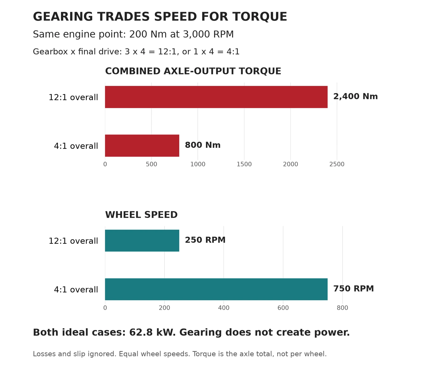
Keep the same final drive but select a 1:1 gearbox ratio, and overall reduction becomes 4:1. At the same engine operating point, the combined output torque is now 800 Nm and the wheels turn at 750 RPM. We have traded torque for speed, not made the engine stronger or weaker.
Short Gearing, Tall Gearing and the Catch
Short gearing means more input revolutions per wheel revolution: a numerically higher overall reduction. It can provide more wheel torque at a given engine torque and keep the engine in a useful RPM range. The trade may be more shifts and higher cruising RPM.
Tall gearing does the opposite. It may lower cruising RPM, but it is not automatically more economical or capable of a higher real top speed. An engine can struggle in an excessively tall ratio, and aerodynamic drag may prevent the car from reaching the speed implied by its gearing.
This is why gear ratios belong beside the torque curve from Part 1. At the same road speed, different gears put the engine at different RPM, where its available torque and power may also differ. Comparing only the multiplication factor misses that second change.
5. AT, DCT and CVT: Three Different Ways to Connect the Power
All three can change ratio without the driver operating a clutch pedal. But the machinery and the sensations can be very different. Here, AT means a conventional torque-converter, stepped automatic; technically, DCTs and CVTs are automatic transmissions too.
AT: Fluid for Launch, Mechanical Coupling When Appropriate
A torque converter transfers energy through moving transmission fluid. The engine drives an impeller, the fluid drives a turbine connected to the gearbox input, and a stator redirects returning fluid. Under suitable launch conditions, that redirection enables torque multiplication.
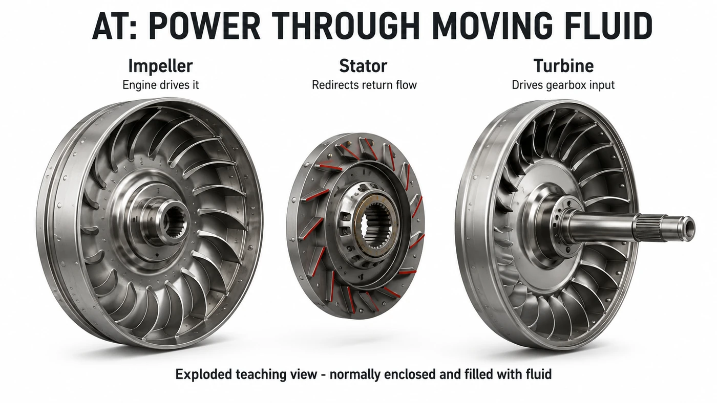
Because the impeller and turbine can rotate at different speeds, the engine can keep running while the car is held stationary. Controlled fluid slip also helps the car move away smoothly. The gearbox behind the converter selects its fixed ratios through gearsets and clutches.
Once conditions allow, a lock-up clutch provides a mechanical connection across the converter, reducing the losses associated with fluid slip. The converter therefore does not have to remain a permanently loose connection. ZF’s torque-converter explanation describes this efficiency role.
Modern stepped automatics can also shift quickly. ZF’s eight-speed 8HP family is a familiar example across road-going rear-drive and all-wheel-drive applications. The number of ratios alone, however, tells us little about how thoughtfully they are selected.
DCT: Prepare the Next Ratio Before the Handover
A dual-clutch transmission divides its gear paths between two clutches, commonly one for odd-numbered forward gears and one for even-numbered gears. While third gear transmits drive through one clutch, fourth can be selected on the other path with its clutch still open.
During the upshift, the controls reduce torque through the first clutch and increase it through the second. That prepared handover can be extremely quick. It does not mean both different ratios are permanently locked to the engine together. Volkswagen’s DSG technical material describes this paired-path principle.
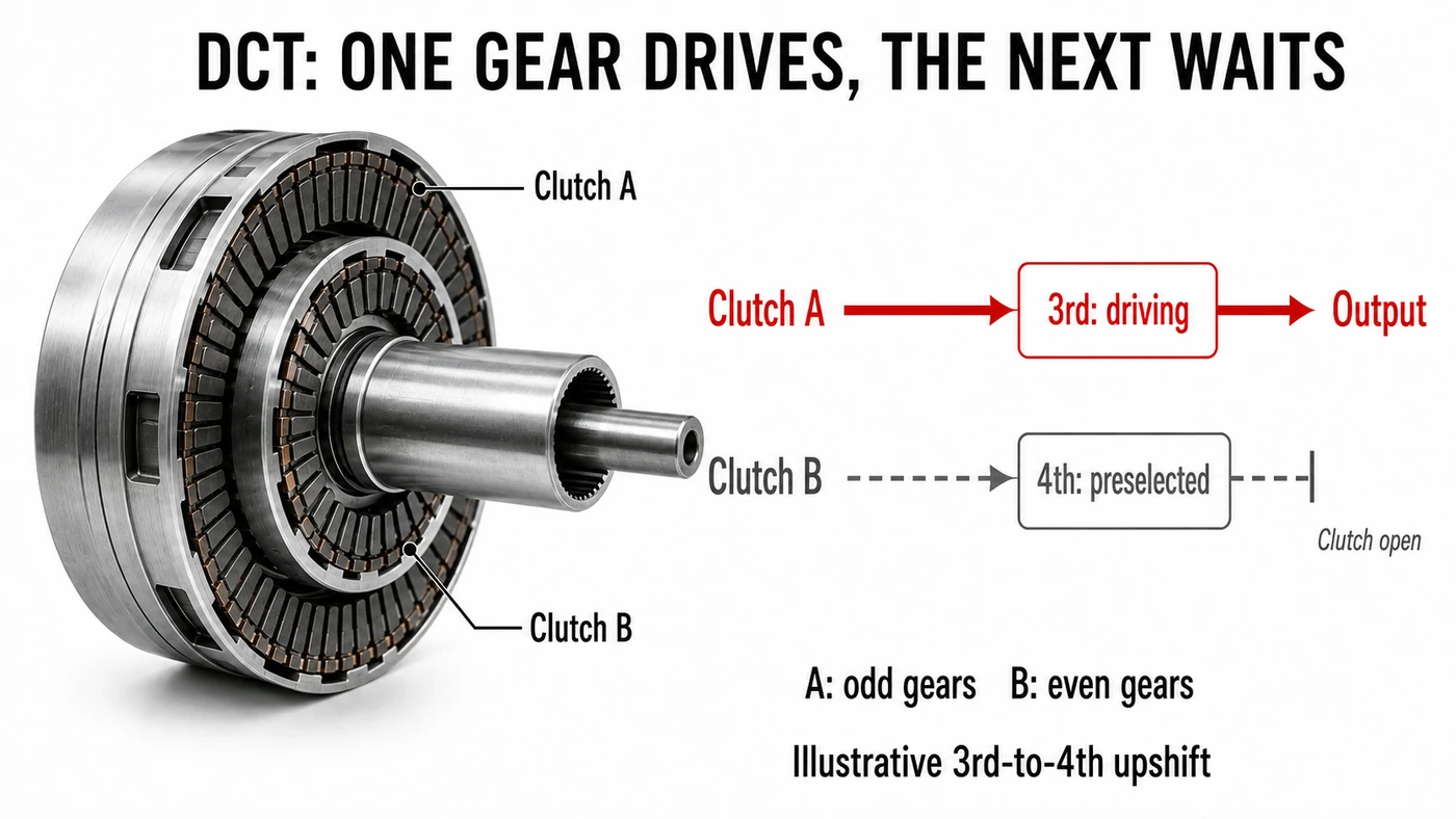
The other side of the story is very low speed. A conventional DCT must manage clutch engagement when launching or creeping, rather than relying on a torque converter. Depending on the design and calibration, that can feel different from a fluid-coupled automatic. Prolonged slipping also produces heat; it is not a reason to diagnose every hesitation as a fault.
Wet clutches run in oil, which helps carry heat away. Dry clutches do not use an oil bath at their friction surfaces. The choice affects thermal behavior and losses, but neither word guarantees reliability. Volkswagen’s DSG overview distinguishes wet and dry implementations. Operation and service should follow the particular vehicle’s manual.
Is a DCT Always Better for a Performance Car?
No. The speed of a prepared upshift is only one task. A sudden request for several lower gears, smooth parking, torque capacity and cooling also matter.
BMW’s G80/G82 M3 and M4 Competition models demonstrate why the answer is not a simple hierarchy: they use an eight-speed M Steptronic automatic with a torque converter. In BMW M’s transmission Q&A, the development team highlights multi-gear changes as one advantage. That does not make every AT faster than every DCT; it makes the actual shift request and implementation important.
CVT: Change the Ratio Without Selecting Fixed Steps
A conventional pulley continuously variable transmission uses a steel belt or chain between two variable-width pulleys. Each pulley has opposing conical faces. Moving those faces changes the radius at which the belt or chain runs, and therefore the ratio.
For a lower output speed relative to the input, the belt runs at a smaller radius on the input pulley and a larger radius on the output pulley. Reversing those working radii raises output speed relative to input. The metal pulley discs do not grow or shrink. Bosch’s pushbelt explanation describes the conical-sheave arrangement.
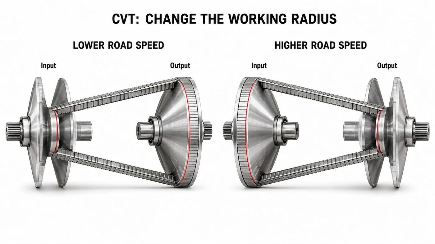
Because the ratio can change continuously, the engine can stay near a chosen RPM while the vehicle accelerates. That can be efficient, but the sound may feel unfamiliar if we expect engine speed to rise and fall with fixed shifts. The often-used description “rubber-band feel” describes that sensation, not a rubber belt stretching inside the transmission.
Some CVTs simulate stepped ratios for a more familiar response. Some also use additional launch hardware: Toyota’s Direct Shift-CVT has a physical launch gear. A CVT may even use a torque converter, so the labels describe different aspects of the mechanism rather than perfectly exclusive boxes.
Toyota e-CVT: Similar Driving Effect, Different Hardware
Do not assume the e-CVT in a Toyota power-split hybrid is a belt CVT with an electric motor attached. In the familiar Toyota arrangement, a planetary power-split device works with motor-generators to manage the relationship between engine speed, electrical power and wheel output.
Toyota identifies its THS II transaxle as a two-motor mechanical power-split type; its 2026 RAV4 technical description explicitly describes the planetary arrangement. Other manufacturers can use different hybrid architectures under similar transmission labels. We will keep the deeper hybrid story separate rather than treating every e-CVT as one mechanism.
Put the Five Ideas Together: Read a Specification Like a Story
Return to our two fictional cars. These combinations are teaching examples, not tested vehicles or claims about which one wins.
| Specification | What we can reasonably infer | What we still cannot know |
|---|---|---|
| 3.0-liter turbo, RWD, eight-speed AT, e-LSD | Rear tires apply the drive; a converter manages launch; fixed ratios and an actively controlled differential shape delivery | Actual acceleration, steering quality, shift response or ride comfort |
| 2.0-liter turbo, FWD, DCT, LSD | Front tires combine steering and drive; two clutch paths handle shifts; an LSD can help reduce the limitation from inside-wheel spin | Whether it feels sharper, is more efficient or is faster around a circuit |
The useful habit is to connect each specification to a question. Where does the driving force enter the road? What happens if one tire unloads? Which engine RPM does the selected gear produce? How does the transmission react when the driver changes their mind?
Those questions also explain why brand reputations are only a starting point. Our AMG, BMW M and Audi RS comparison explores the philosophies; the hardware in a particular model tells us how those ideas are implemented.
Common Misconceptions Worth Leaving Behind
- AWD makes every car handle and stop better. It adds ways to apply driving torque, not an exemption from tire limits.
- Different wheel speeds mean wheelspin. On a bend, they are often exactly what rolling geometry requires.
- An open differential sends all torque to one wheel. Its approximately equal output torque is precisely why one low-grip side can limit the other.
- An LSD is always fully locked. Most manage resistance or torque bias; some active designs can additionally reach full lock under selected conditions.
- Short gearing creates horsepower. It exchanges rotational speed for torque, with losses along the way.
- DCT, AT and CVT are a best-to-worst ranking. The names describe mechanisms, not the quality of their implementation.
Cariary Thoughts
The most useful shift in thinking for us is moving from “How much power does it have?” to “What can the car do with that power right now?” A horsepower figure is still meaningful. It simply cannot describe a loaded outside tire, an open clutch waiting for the next shift or an engine sitting in the wrong part of its rev range.
The differential is a particularly good example. Letting wheels turn at different speeds is essential for an ordinary corner, yet the same freedom needs managing when one tire loses traction. The engineering is not correcting a pointless flaw. It is balancing two genuine needs that can pull in different directions.
That is what makes learning these parts enjoyable. The acronyms stop being badges to rank and become explanations for sensations we already recognize. We do not need to dismiss one transmission or drivetrain to appreciate why another was chosen.
One-line Summary
The drivetrain turns engine output into a driving experience by choosing the wheels, managing their differences and trading rotational speed for usable torque.
FAQ
What is the difference between a drivetrain and a powertrain?
Powertrain usually includes the engine or motor together with the components that deliver its output. Drivetrain generally refers to the delivery components after the power source. Usage varies, but separating production from delivery is a helpful starting point.
Does a front-wheel-drive car have a differential?
Yes. A conventional FWD car normally has one integrated into its transaxle. It may be less visible than the separate rear assembly on a RWD car, but the front driven wheels still need to turn at different speeds.
Does AWD mean a car also has an LSD?
No. Front-to-rear torque management and left-to-right differential behavior are separate questions. An AWD car may combine open axle differentials, brake-based traction control, clutch units or other hardware. Check the specific system.
Can a car have both an LSD and traction control?
Yes. Mechanical or electronically controlled differential hardware can work alongside traction and stability controls. Software may manage engine torque and brakes as well as differential locking; the systems need not be alternatives.
Is a higher final-drive number shorter gearing?
With the gearbox ratio and tire size unchanged, yes. A 4.10:1 final drive is shorter than a 3.50:1 final drive. It requires more engine revolutions per wheel revolution and multiplies torque more, before accounting for losses.
Why can engine RPM stay high while a CVT car accelerates?
The transmission can change its ratio while the engine remains near a chosen operating speed. Rising road speed therefore does not require the familiar climb-and-drop pattern of a stepped gearbox. That behavior alone does not prove abnormal belt slip.
Is a Toyota hybrid e-CVT the same as a normal belt CVT?
No. The Toyota power-split arrangement discussed here coordinates planetary gearing and motor-generators instead of using variable pulleys and a belt. Similar driving behavior does not mean identical internal machinery.
Related Thoughts
- Part 1: Engine Power Basics: the torque, RPM and horsepower ideas that gearing builds on.
- FWD vs RWD vs AWD: connect the layouts to driving environments and everyday use.
- AMG vs BMW M vs Audi RS: see how different performance philosophies shape real cars.
References
Data reference date: September 7, 2026. Vehicle examples refer to the documented generations, not every model carrying the same badge. Numerical examples and charts are Cariary teaching calculations, not vehicle test data. Generated images simplify the stated principles and are not service drawings or exact manufacturer components.
- Eaton: limited-slip differential principles, Posi clutch-pack arrangement and IntelliTrac electronic control.
- Torsen: torque-bias FAQ and traction-limit explanations.
- Magna: AWD disconnect technology and Ford: four-wheel-drive operating guidance.
- ZF: 8HP transmission family and torque-converter lock-up function.
- Volkswagen: DSG gear-path explanation and concentric input-shaft technical document.
- BMW M: M3 and M4 Competition transmission Q&A.
- Bosch: CVT pushbelt and conical pulleys.
- Toyota: Direct Shift-CVT, THS II power-split transaxle and RAV4 hybrid architecture.